Vacuum Components

Custom Bent Tubing & Freeform Welded Assemblies

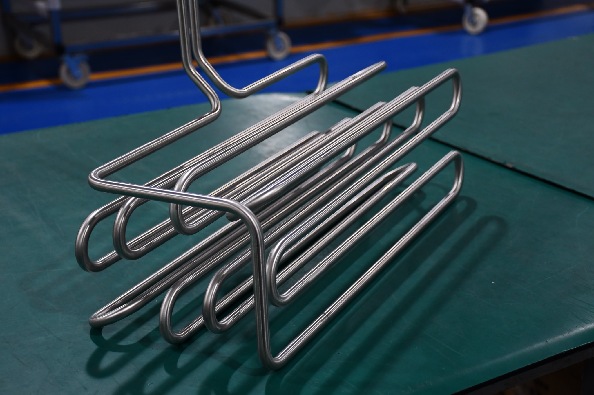
Freeform bent and welded products for drawing-defined three-dimensional routing, coiled paths and branching assembly layouts.

03 / CUSTOM SPATIAL ROUTING

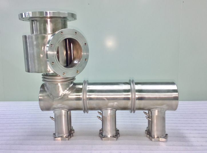
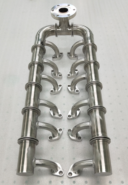
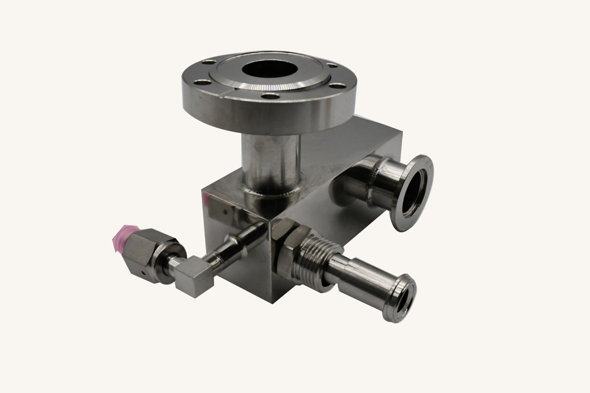
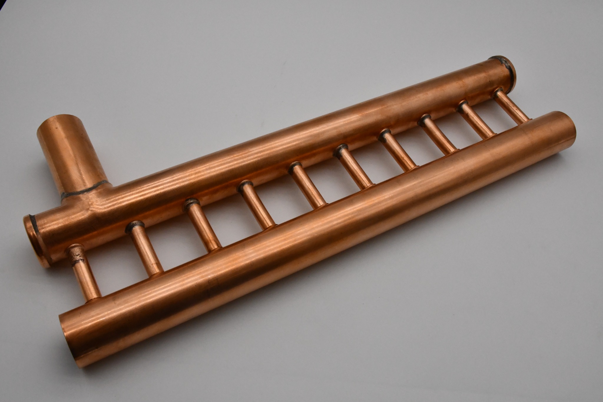
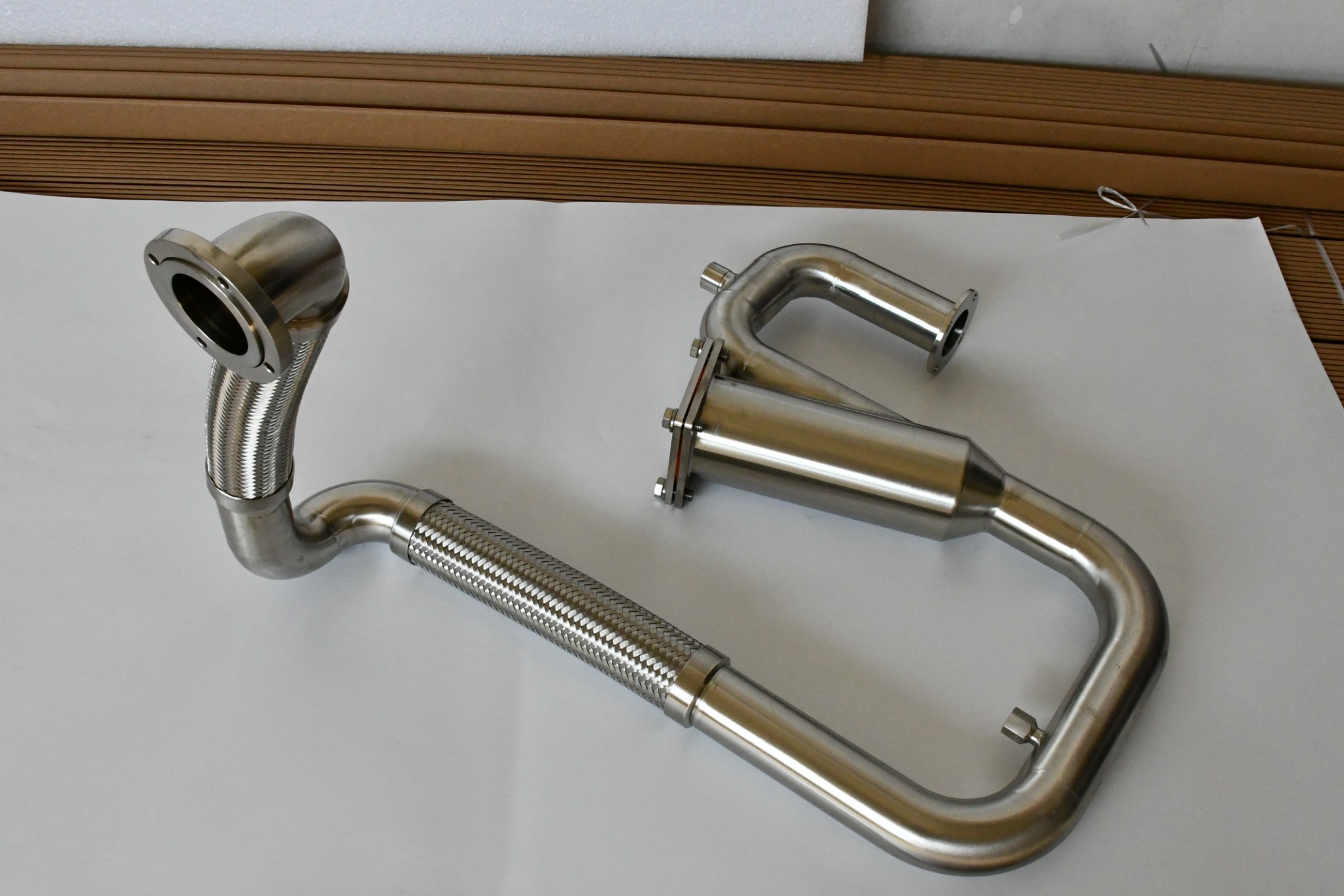
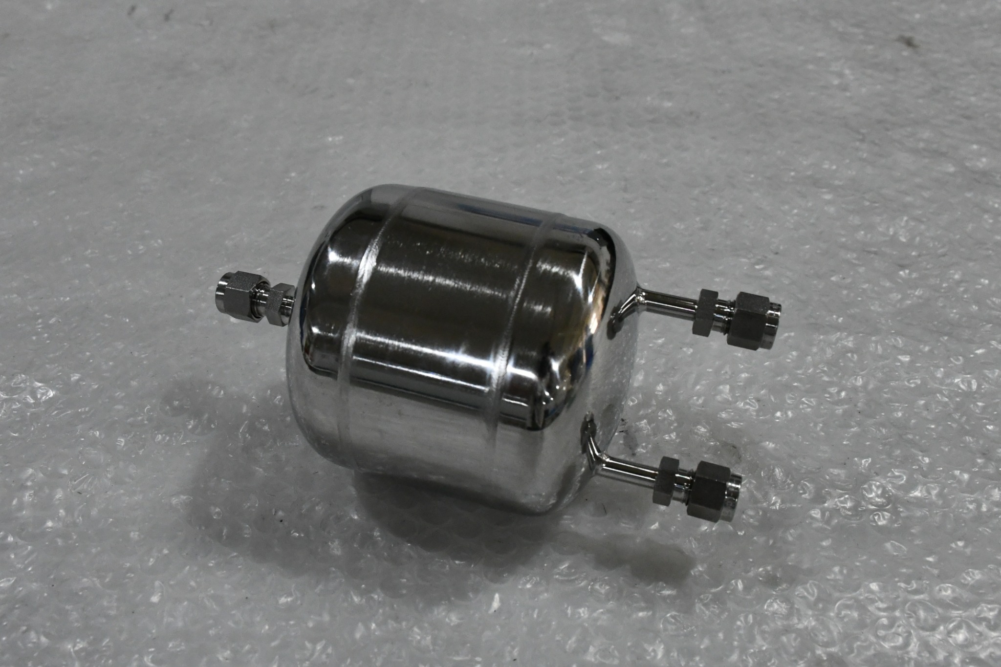
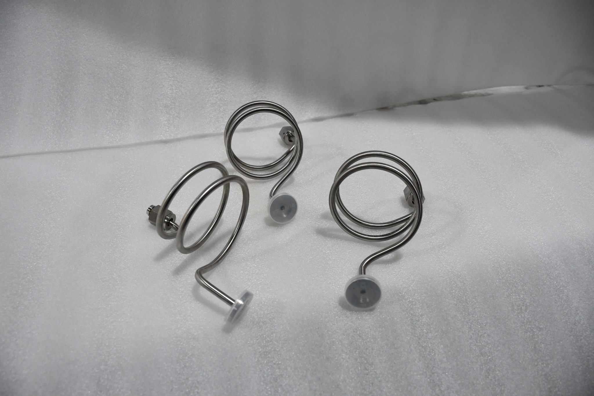
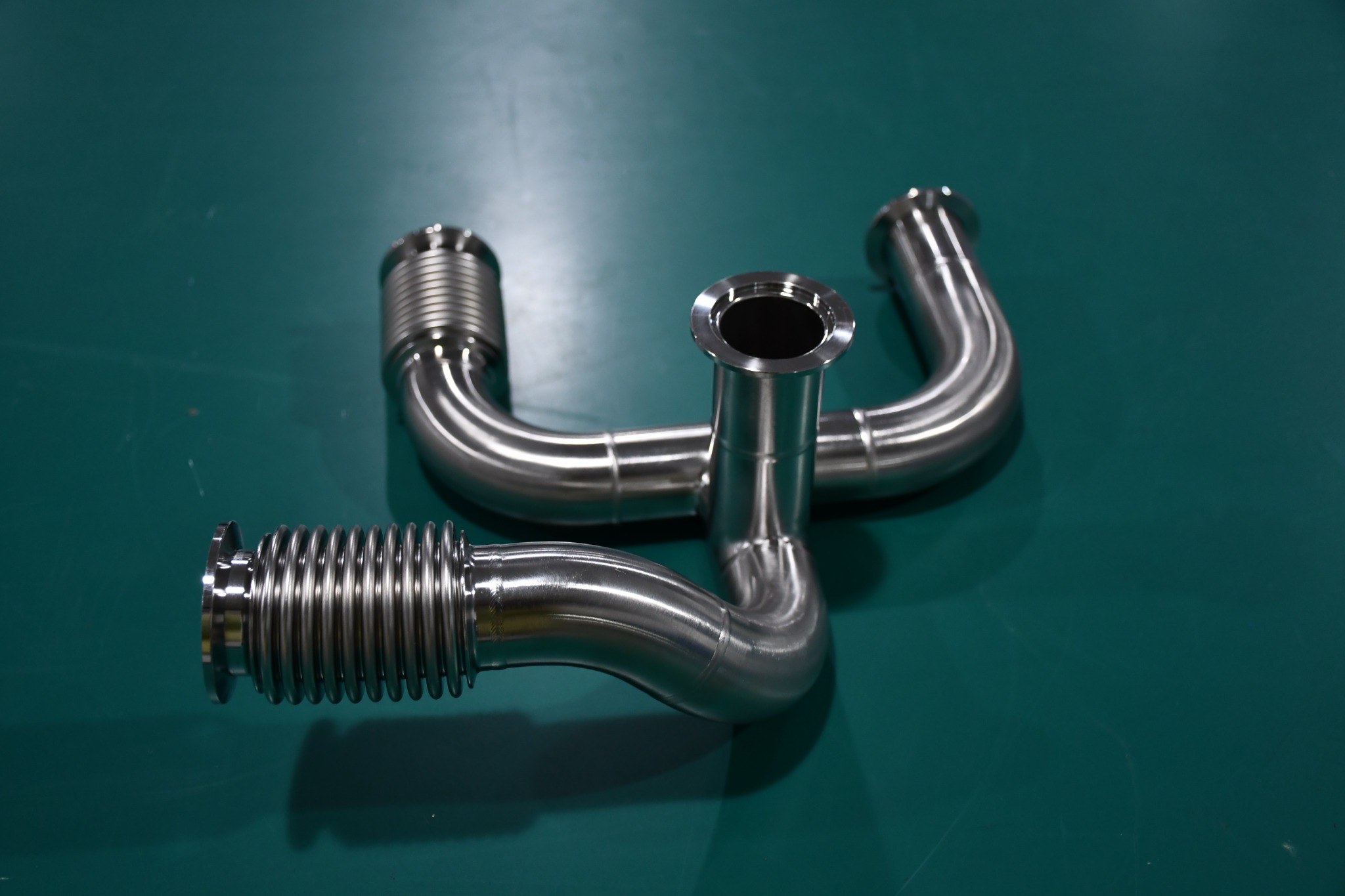
Freeform routing & assembly examples

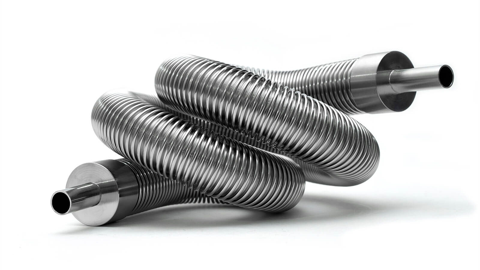
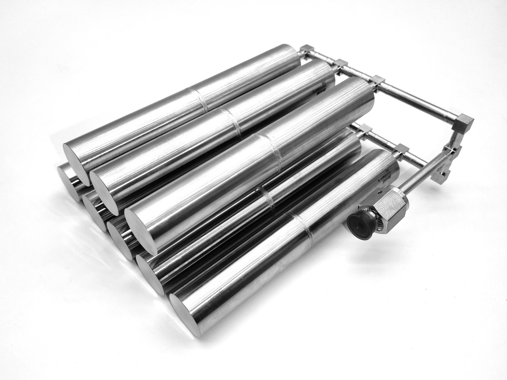
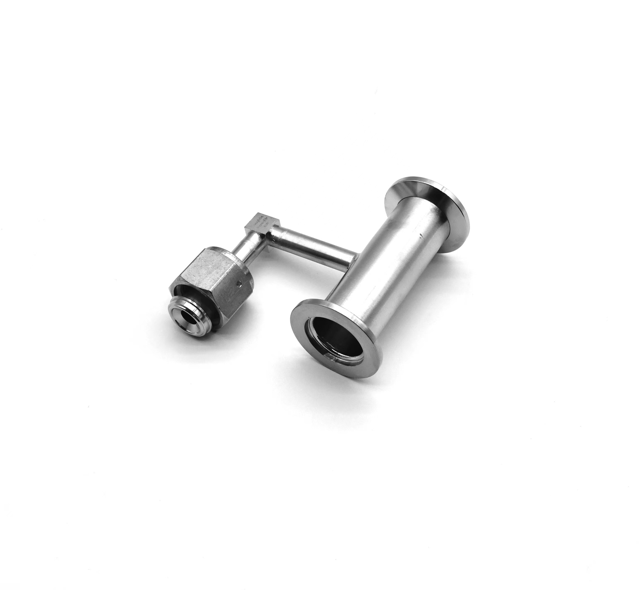
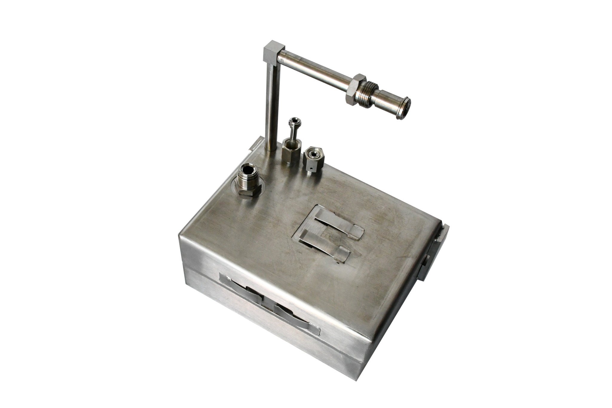
Custom-shaped tubes, manifolds and welded assemblies arranged around the available installation space. Explore coiled paths, return bends, branching layouts and combinations of rigid and flexible sections.

  • Define three-dimensional routing, bend radii, angles and end orientations
  • Combine branches, manifolds and selected flexible sections to suit the design
  • Share a drawing or 3D model, materials, tolerances and operating conditions
Discuss this product area →
Multi-plane formed tube layouts

Click a photo to view it at full size. Final specifications are confirmed against the selected drawing.

Applications & selection

Custom tube routing & assembly selection

Multi-plane bends and return loops

Use a drawing or 3D model to define the route, end positions and connection orientations.

Coiled tubing and parallel headers

Specify coil or header geometry, spacing, connection details and the available installation envelope.

Welded manifolds and mixed sections

Define branch locations and any bellows or braided section separately from the rigid tube path.

Information to include in your enquiry
RequirementDetails to provide
Routing geometry3D path, bend angles, bend radii and end orientations
Fit and interfacesClearances, port positions, mounting points and mating connections
Manufacturing requirementsMaterial, tube dimensions, surface finish and tolerances
Service requirementsMedium, operating conditions and any movement assigned to a flexible section

Final configuration and acceptance criteria are reviewed against the drawing or representative samples.

Before you enquire

Assembly selection questions

Does freeform mean the finished tube can bend freely in service?

Here, freeform describes a custom-shaped route. The rigid portions follow the specified geometry. Any movement requirement must be assigned to an appropriate flexible section.

What design files should I provide?

Send a dimensioned drawing or 3D model showing routing, clearances, bend radii, end orientations and mounting points. Add material, finish and tolerance requirements.

Can a design combine branches and flexible sections?

The supplied examples show branching layouts and selected flexible sections. Their suitability and assembly details are confirmed during drawing review.

Discuss your requirements.

Share your drawing, sample details or operating conditions.

Prepare an enquiry →